Product Design Studio
Conceptualized and Completed by Ooi Jia Sheng (1003424)
Automated Cooling System through Movement Monitoring
Introduction
Singapore is a hot and humid nation where one must be wary of their body temperature if significant portion of the day is spent moving around ourdoors. This leads to a probable chance of inducing heatsroke or other forms of heat injury in the process. The product seeks to cool the bodies of the user by increasing rate of sweat evaporation when non-stantionary. An Arduino System is embedded to the user and functionalities cna be controlled by a Android application. The system comprises of an app-based user interfacce, a database hosted on a cloud and a embedded system using an Arduino Development Board embedded with a WiFi module. The individual modules communicates using WiFi communication protocols.
Bill Of Materials
| Index | Component | Description |
|---|---|---|
| 1 | Arduino MKR WiFi 1010 | Development Board to control input and output modules |
| 2 | Phone with Android OS | User Interface(MIT App Inventor 2) to allow user to adjust settings |
| 3 | SparkFun H3LIS331DL Triple Axis Accelerometer Breakout | Provide X,Y,Z acceleration readings to detect user’s motion |
| 4 | LED (Green) | Status light to indicate key events |
| 5 | 3V DC Motor | Power the fan to cool the body |
| 6 | Fan Blade | Generate directional wind current to increase rate of sweat ecaporation |
| 7 | L295N Motor Driver | Facilitate speed control of the DC Motor |
Specifications
Arduino MKR WiFI 1010
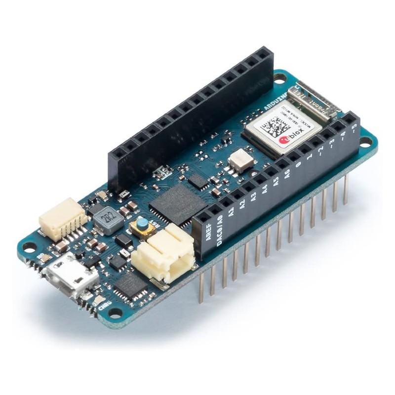
- Board Input Voltage : 5V
- Communication: Wifi & Bluetooth
- Dimensions: 61.5mm x 25mm
SparkFun H3LIS331DL Triple Axis Accelerometer Breakout
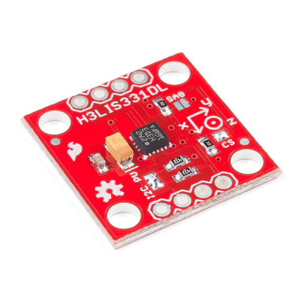
- Board Input Voltage: 2.16V to 3.6V
- Digital Output: I2C & SPI
User Interface

- Android based Application
- Built using MIT App Inventor 2
- Number below slider refers to the phone internal accelerometer reading (not used)
System Architecture
Circuit Diagram

Database
 The database provides a middleman platfrom for the Android application and the Arduino system to facilitate communication. THe database uses the Firebase api, specifically its realtime database. The above variables are used in the project, which will be elaborated below.
Communication

*Enable: Controls whether the fan can be activated or not, if the user is in motion. *Power: Controls the fan speed when the fan is on. *Pitch: The rotation around X axis measured by the accelerometer *Roll: The rotation around Y axis measured by the accelerometer
Workflow of Product
Setup
Ensure that a realtime database has been set up and is ready to be used. Adhere to the circuit diagram and Bill Of Materials with the associated code while using the AI2 file to interface with it.
Bootup
At iniital boot up of the Arduino, it will establish communication with the WiFi of choice (in this context it will be SUTD_IOT). Upon successful connection, the green LED will light up. Sequentially, the Arduino will set up communication with the Firebase API.
Main Functionality
The default case without the Android Application will be that the fan will not turn on regardless of motion. After the Android Applicatio is live and the user has clicked on the ‘enable’ button, the fan will be able to fucntion upon movement is detected. The movement that the product tracks is gneralised to a substantial change in the pitch value,
To actuate the DC Motor, a L298N Motor Driver is used to control the speed of the fan using Pulse Width Modulation (PWM) Technoques.
Throughout the run cycle of the product, multi-threaded control is implemented on the Arduino, such that controlling the motor/monitoring the 3 Axis Acceleormeter values and montioring Firebase for change in Enable and Power, that enables the fan use and fan speed respectively.
Mobile Application
Enable/DIsable control
Fan Speed Change
Code
Conclusion
The product has managed to deliver the intended outcome, where a certain level of motion can be dected using the acceleormeter rreadings to contorl the fan, thought the condition has been very generalized. Possible expansion of the project is to soley rely on the phone sensor readings, thus requiring a much more from fitted system where there is only the fan and a smaller controller (ESP 32).
Acknowledgments
- Arduino MKR WiFI 1010
- Firebase
- MIT App Inventor 2